Formulation of the beam-column elements > Bar or truss elements
Figure 27 shows a straight bar whose nodal degrees of freedom are axial and transversal displacements (ui, vi, uj, vj). A linear displacement field is appropiate.
 |
(78) |
Imposing the limit conditions the displacement field can be rewriten as:
 |
(79) |
where the shape functions Ni are:
 |
(80) |
and in which 
.
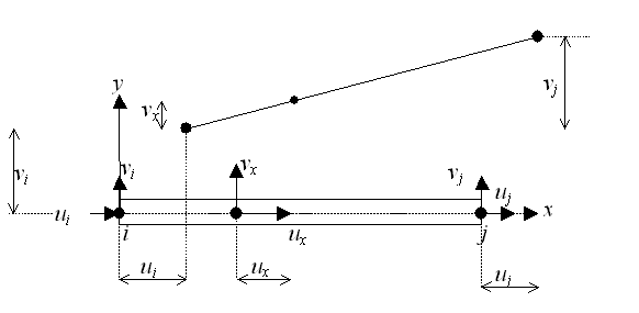 |
| Figure.27. Truss element. |
The axial strain along the element legth is defined as:
 |
(81) |
or in the matrix condensation form the displacements and strains relationships can be expressed as:
 |
(82) |
where
 |
(83) |
and represents the strain-displacement operator.
The element stiffness matrix is computed in this case as:
 |
(84) |
Where EA represenst tha axial stiffness of the element (E is Young modulus, A cross-section area) and L the element length. The stiffness matrix k defined above relates axial forces at the nodes, to the axial displacements at the nodes, and represents the stiffness
matrix in the local element system. If the bar is oriented at an angle β in the xy plane, the matrix must be trnasformed by a rotation matrix as:
 |
(85) |
where for the xy plane the rotation matrix is:
 |
(86) |
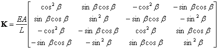
The element stiffness matrix in the global coordinates system becomes:
 |
(87) |
© GeoStru Software